
In engineering, when you hear the words reference frame, you will also see the associated drawing of three vectors that point in three directions. Like this one:
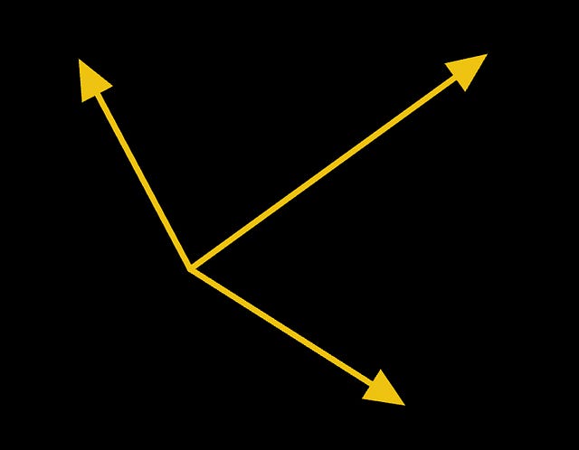
The thing is that this drawing using arrows refers to a Coordinate system, which is a different concept. Let’s see.
The definition of a Reference frame is a collection of fixed points with respect to each other. This means that anything rigid (not deforming) can be taken as a reference frame. This definition does not need us to specify directions or anything similar. We only need a rigid reference!
In practice, a reference frame is a physical or imaginary object that we use as a baseline to observe motion or changes.
A reference frame provides a way to observe motion, but it does not provide a way to measure motion. This means that if all we have is a reference frame, we can only perceive motion — or the lack of it. But we cannot quantify the motion. To measure motion, we need a Coordinate system.
A coordinate system is introduced to measure motion.
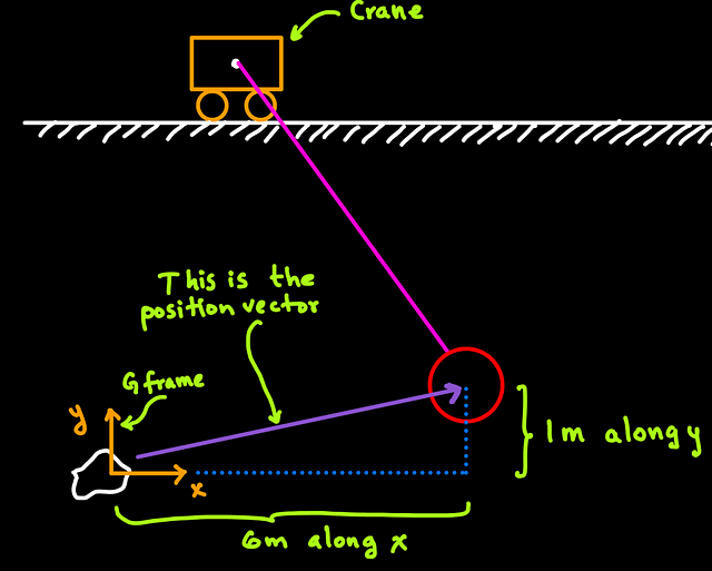
When a coordinate system is overlayed on a reference frame, then we can observe AND measure motion. Classic definitions of a coordinate system may include labels on the directions along which motion is measured, like in this figure:

The concepts of a Reference frame and Coordinate system are very related, which is why they are commonly used as synonyms. However, now you know that, in definition, they are different.
In summary,
A reference frame is a collection of points that allows one to observe motion, but it does not provide a way to measure the motion.
A Coordinate system allows us to measure motion. A coordinate system is attached to a reference frame.
TIP: The same reference frame can be the home of an infinite number of coordinate systems.
Inertial reference frame
A reference frame can move. For example, when a spaceship travels to the moon, our reference frame can be attached to Earth because we want to know how far the spacecraft has traveled with respect to us. There is no problem in defining a moving reference frame.
However, when applying Newton’s laws, we will need to define an inertial reference frame — Newton’s laws assume that such frames exist.
An inertial reference frame is a frame that is fixed, or that is moving at a constant velocity at most.
If you have ever seen or heard seconds Newton’s law, F=ma (Force equals mass times acceleration), well, that acceleration needs to be computed with respect to an inertial frame.
BONUS: Moving and inertial frames in the same application?
It is common in engineering to have inertial and moving frames simultaneously to analyze a problem. A drone (quadcopter) is an excellent example of this. In the following figure, we see the inertial frame n+ and the drone body frame b+.

While the n+ frame is fixed and used to compute inertial quantities with respect to it, the body frame b+ is helpful because the propeller’s thrust and torques are more easily represented in this b+ frame. In other words, in the b+ frame, the propellers always push “up” along the b3 direction. We could only use the inertial frame for the propeller’s thrust. Still, we need to appropriately account for the drone tilting to correctly represent the thrust in the n+ frame.
In any case, it is up to the engineer to choose the frames and their location to what he/she thinks is more convenient.
Reference frames and their corresponding coordinate system can be placed anywhere. It is up to us to decide what is more convenient!

Leave a comment